J1939 Examples
Receive and send SPNs from a QML application
This example shows how to create a QML application and update it using LinX Manager Fieldbus Access to send and receive J1939 data on the CAN bus.
Prerequisites
Data Engine installed on target device.
Fieldbus Access installed on target device.
Interface
can0is up.can-utilsinstalled.
Data Engine and Fieldbus Access is pre-installed on UX Designer VM 4.0. Newer versions can be downloaded from the support site.
Create a QML project
Create a new project to use through the example.
Open Qt Creator.
File>New file or Project....Select
CrossControl Projectand pickQt Quick 2 Application.Follow the on-screen instructions to finalize the project creation:
Display resolution: 800x480
Kit: Desktop

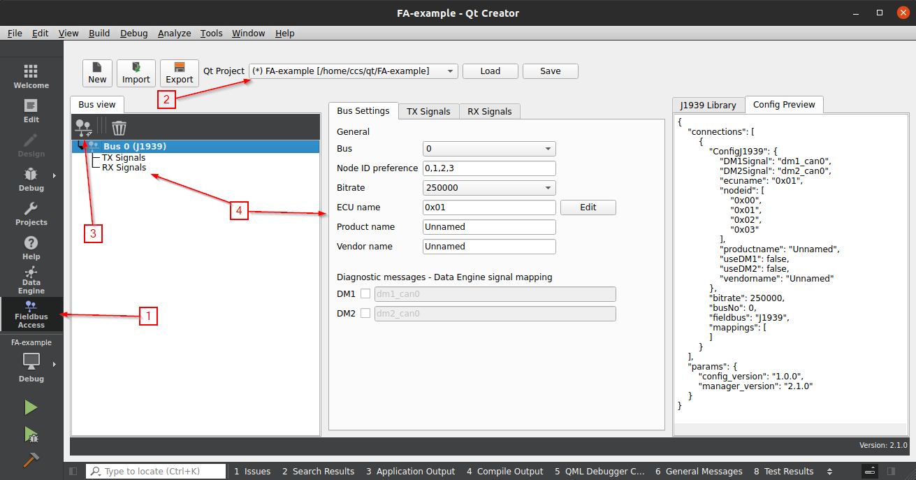
Create a new J1939 bus
Open LinX Manager Fieldbus Access from the mode selector (left side).
Select the created project from the project selector drop-down menu.
Create a new CAN bus by pressing the add button
 and select
“Add new J1939 bus”.
and select
“Add new J1939 bus”.An empty J1939 bus is created with default settings.
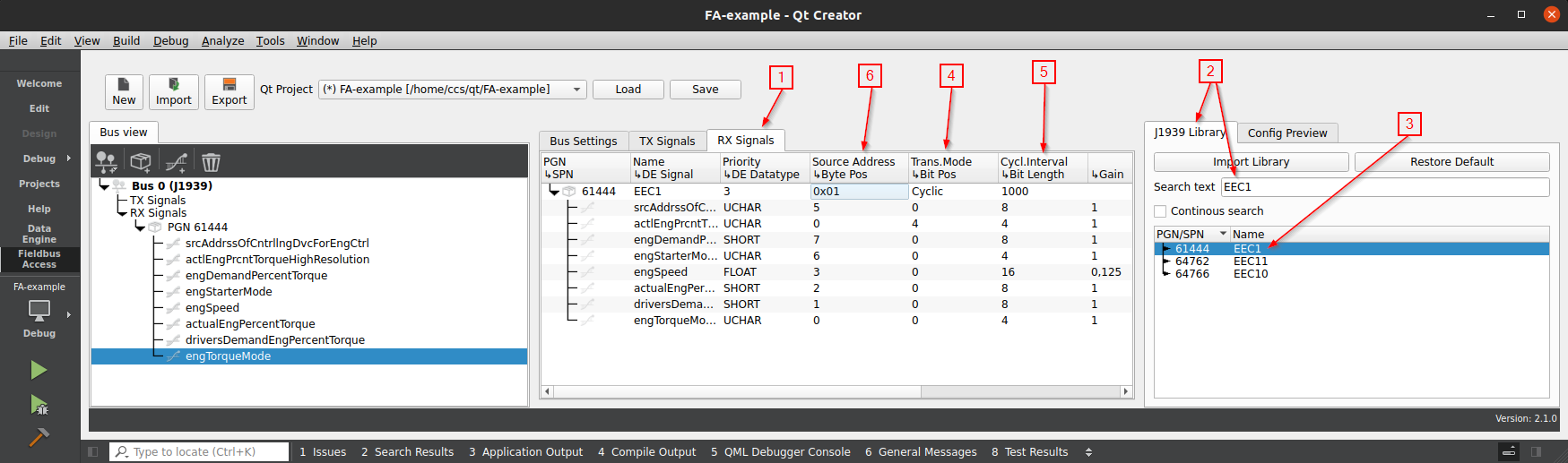
Add receive (RX) signals from the library
Select “RX Signals” tab from the middle panel.
Open the J1939 Library tab on the right-most side and search for “EEC1”.
Drag EEC1 (61444) from the library into the RX panel. PGN is created with associated SPNs.
Update “Transmission Mode” to
Cyclic(red cells indicate missing information).Update “Cyclic Interval” to
1000 ms(PGN is expected to be received once every second).Update “Source Address” from
0xFFto0x01(PGN should only be received from Node ID0x01).
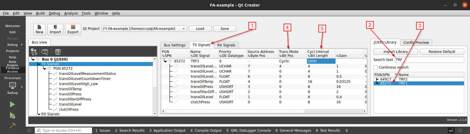
Add transmit (TX) signals from the library
Select “TX Signals” tab from the middle panel.
Search for “TRF1” in the J1939 library.
Drag TRF1 (65272) from the library into the TX panel. PGN is created with associated SPNs.
Update “Transmission Mode” for TRF1 to
Cyclic.Keep “Cyclic Interval” at
1000 ms(PGN should be transmitted once every second).
Update the project
With the two PGNs created, the last step to perform with the plugin is to export the configuration and update the active project.
From the projector selector, press “Save” for the changes to take effect.
Verify that the project was updated by opening the General Messages tab (
Alt+6):LinX Manager Data Engine: Project updated successfully.
Selected project is now updated with new code and files. See How-tos for a complete list of generated files.
Snippet from dataengine.h:
class DataEngine : public DataEngineBase
{
    Q_OBJECT
    // Generated Signal MetaProperties
    Q_PROPERTY (QByteArrayConsumerSignal* fieldbusAccess_J1939Error_CAN0 READ fieldbusAccess_J1939Error_CAN0 CONSTANT)
    Q_PROPERTY (UCharConsumerSignal* srcAddrssOfCntrllngDvcForEngCtrl READ srcAddrssOfCntrllngDvcForEngCtrl CONSTANT)
    Q_PROPERTY (UCharConsumerSignal* actlEngPrcntTorqueHighResolution READ actlEngPrcntTorqueHighResolution CONSTANT)
    Q_PROPERTY (ShortConsumerSignal* engDemandPercentTorque READ engDemandPercentTorque CONSTANT)
    Q_PROPERTY (UCharConsumerSignal* engStarterMode READ engStarterMode CONSTANT)
    Q_PROPERTY (FloatConsumerSignal* engSpeed READ engSpeed CONSTANT)
Display SPN in QML
Values from the CAN-bus can now be visualized directly in the UI using the context property dataEngine. The
documentation for LinX Manager Data Engine contains further instructions how to use the context property (both from
QML and Widget projects).
Open
main.qmlwith the editorLocate
// add your GUI code below this lineAdd the following to display
engSpeedandactualEngPercentTorquesignals in a Text component:Text { id: engSpeed color: dataEngine.engSpeed.status ? "red" : "white" text: dataEngine.engSpeed.value } Text { id: actualEngPercentTorque color: dataEngine.engSpeed.status ? "red" : "white" anchors.top: engSpeed.bottom text: dataEngine.actualEngPercentTorque.value }
PGNs which has the transmission mode set to Cyclic has timeout detection activated. The status is accessed using
dataEngine.[signal].status. More of this can be read in Error handling.
Set a SPN from QML
The snippet below will create two buttons in QML. When the first is clicked, it will update the SPN transOilTemp (part
of PGN TRF1) and set the value to -50. When the second button is clicked, it will update the same SPN again and set the
value to 100. The value will be visible on the CAN bus when Fieldbus Access is running (future step).
Add this snippet beneath the code added in the previous section:
Rectangle {
    id: lowTransTemp
    width: 220;  height: 60
    anchors.top: actualEngPercentTorque.bottom
    color: btnMouseArea1.pressed ? Qt.darker("grey", 1.5) : "grey"
    Text {
        anchors.centerIn: parent
        text: "Set low transmission temp"
    }
    MouseArea {
        id: btnMouseArea1
        anchors.fill: parent
        onClicked: dataEngine.transOilTemp.value = -50
    }
}

Rectangle {
    id: highTransTemp
    width: 220;  height: 60
    anchors.top: lowTransTemp.bottom
    color: btnMouseArea2.pressed ? Qt.darker("grey", 1.5) : "grey"
    Text {
        anchors.centerIn: parent
        text: "Set high transmission temp"
    }
    MouseArea {
        id: btnMouseArea2
        anchors.fill: parent
        onClicked: dataEngine.transOilTemp.value = 100
    }
}
Start Fieldbus Access with generated configuration
The application is now prepared to send and receive value from/to the CAN bus. What’s left is to run Data Engine and Fieldbus Access to let it handle the CAN-communication.
Start Data Engine using the desktop shortcut.
Locate the generated configuration file for Fieldbus Access in the project directory.
[project directory]/LinXManager_FieldbusAccess/LinXManager_FA_configfile.json.Drag and drop the configuration on the Fieldbus Access shortcut found on the desktop.
Fieldbus Access start to execute based on the information found in the configuration.
Fieldbus Access will start and send PGN TRF1 to the CAN bus since this was added to TX signals. Open a terminal and use
the command candump can0 to view the traffic which is sent by Fieldbus Access to the CAN bus. The frame is filled with
0xFF since no values have yet been written to the SPNs in the PGN.
ccs@LinX-VM:~$ candump can0
  can0  18FEF800   [8]  FF FF FF FF FF FF FF FF
  can0  18FEF800   [8]  FF FF FF FF FF FF FF FF
  can0  18FEF800   [8]  FF FF FF FF FF FF FF FF
  can0  18FEF800   [8]  FF FF FF FF FF FF FF FF
Send random SPN data and view in QML
With Data Engine and Fieldbus Access running from the previous step, it is now possible to read data from the CAN bus and display the result in the application created earlier.
Compile and start the application from Qt Creator.
Text fields for
engSpeedandactualEngPercentTorqueare displayed in red with the value assigned to zero.Open a terminal and use
cangento generate random data for EEC1.# Send 8 random bytes every second as node ID 0x01 to PGN 61444 (0xF004) ccs@LinX-VM:~$ cangen can0 -e -I 0CF00401 -L 8 -g 1000 -v can0 0CF00401#E2.C1.08.7B.39.86.03.4A can0 0CF00401#9F.4A.78.58.CE.D8.C2.42 can0 0CF00401#C8.09.FE.73.BB.D5.6E.35 can0 0CF00401#CE.11.D4.62.A3.49.F5.0F
Values for
engSpeedandactualEngPercentTorqueis updated based on the values sent on the CAN bus. Color of the text is updated from red to white when the status SPNs changes.
Set a SPN from QML (continued)
Pressing any of the two buttons will update transOilTemp and later sent to the CAN bus by Fieldbus Access. The
physical value from the application is scaled with the configured gain and offset before it is visible on the CAN bus.
| Physical | Offset | Gain | Raw (hex) |
|---|---|---|---|
| -50 | -273 | 0.03125 | 0x1BE0 |
| 100 | -273 | 0.03125 | 0x2EA0 |
Use candump can0 to view the CAN frames sent by Fieldbus Access:
ccs@LinX-VM:~$ candump can0
  can0  18FEF800   [8]  FF FF FF FF FF FF FF FF
  can0  18FEF800   [8]  FF FF FF FF E0 1B FF FF # "Set low transmission temp" button pressed
  can0  18FEF800   [8]  FF FF FF FF E0 1B FF FF
  can0  18FEF800   [8]  FF FF FF FF E0 1B FF FF
  can0  18FEF800   [8]  FF FF FF FF A0 2E FF FF # "Set high transmission temp" button pressed
  can0  18FEF800   [8]  FF FF FF FF A0 2E FF FF
Create custom PGNs (PDU2)
The application in this example should receive joystick controller available on the CAN bus. The node ID of the joystick
controller is set to 0x01 and data is transmitted with 10 Hz.
The following information is known about the PGN and the associated SPNs:
| Parameter Group Name | Joystick controller |
|---|---|
| Parameter Group Number | 65283 |
| Transmission rate | 100 ms |
| Data length | 8 bytes |
| Default priority | 6 |
| Data page | 0 |
| PDU format | 255 |
| PDU specific | 3 |
| Data description | See below |
| Byte | Data description | Data length | Offset | Scale |
|---|---|---|---|---|
| 0.0 | D-pad right | 1 bit | 0 | 1 |
| 0.2 | D-pad left | 1 bit | 0 | 1 |
| 0.4 | D-pad up | 1 bit | 0 | 1 |
| 0.6 | D-pad down | 1 bit | 0 | 1 |
| 1.0 | Joystick rotation left | 2 byte | 0 | 1 |
| 3.0 | Joystick rotation right | 2 byte | 0 | 1 |
| 5.0 | Button start | 1 bit | 0 | 1 |
| 5.2 | Button A | 1 bit | 0 | 1 |
| 5.4 | Button B | 1 bit | 0 | 1 |
| 5.6 | Button X | 1 bit | 0 | 1 |
| 6.0 | Button Y | 1 bit | 0 | 1 |
| 6.2 | Button L | 1 bit | 0 | 1 |
| 6.4 | Button R | 1 bit | 0 | 1 |
| 7.0 | Future (not used) | 1 byte | 0 | 1 |
Create PGN and SPNs
Given the information about the controller and the description of the PGN and SPNS
Create a new J1939 CAN bus.
Create one new RX PGN and enter the information found in the PGN table below.
With the PGN selected, create 13 new SPNs and update these using the information found in the SPN table below.
From the projector selector, press “Save” for the changes to take effect.
| PGN | Name | Priority | Source Address | Transmission Mode | Cyclic Interval |
|---|---|---|---|---|---|
| 65283 | Joystick controller | 6 | 0x01 | Cyclic | 100 |
| SPN / DE Signal | DE Datatype | Byte Pos. | Bit Pos. | Bit Len. | Gain | Offset |
|---|---|---|---|---|---|---|
| dPadRight | BOOL | 0 | 0 | 1 | 1 | 0 |
| dPadLeft | BOOL | 0 | 2 | 1 | 1 | 0 |
| dPadUp | BOOL | 0 | 4 | 1 | 1 | 0 |
| dPadDown | BOOL | 0 | 6 | 1 | 1 | 0 |
| joystickRotationL | USHORT | 1 | 0 | 16 | 1 | 0 |
| joystickRotationR | USHORT | 3 | 0 | 16 | 1 | 0 |
| buttonStart | BOOL | 5 | 0 | 1 | 1 | 0 |
| buttonA | BOOL | 5 | 2 | 1 | 1 | 0 |
| buttonB | BOOL | 5 | 4 | 1 | 1 | 0 |
| buttonX | BOOL | 5 | 6 | 1 | 1 | 0 |
| buttonY | BOOL | 6 | 0 | 1 | 1 | 0 |
| buttonL | BOOL | 6 | 2 | 1 | 1 | 0 |
| buttonR | BOOL | 6 | 4 | 1 | 1 | 0 |
Refer to Receive and send SPNs from a QML application for further information how to access SPNs from the application.
Consideration when creating custom PGN and SPN
Each SPN is sent to the application as a Data Engine signal. It is therefore important to verify that the selected datatype (DE Datatype column) is large enough for carry the physical value (scaling and offset applied to raw value).
The name of the SPN in the “DE Signal” column must start with a lowercase letter. This restriction is automatically applied by the tool when entering a name.
Display J1939 errors in a table view
The tool injects the project with a model which stores J1939 stack errors. Information stored in the model can be
displayed in QML, for example with a ListView or TableView. The model is accessed via the context property
j1939ErrorModel-
Example of a ListView in QML which displays four roles from the error model:
ListView {
    width: parent.width
    height: parent.height

    model: j1939ErrorModel

    delegate: Row {
        width: parent.width
        spacing: 25
        Text {
            text: bus
        }
        Text {
            text: addInfo
        }
        Text {
            text: level
        }
        Text {
            text: description
        }
    }
Cyclic timeout detection for J1939 SPNs in QML
RX PGNs which have the transmission mode set Cyclic will be tracked by Fieldbus Access for reception. A PGN is
regarded as missing if it is not received within an expected time window (cyclic interval x 3). Fieldbus Access will send
an error signal each time this occurs. Another error signal is transmitted when the PGN is received, allowing the
application to know that the PGN and associated SPNs are valid.
This feature is unique for cyclic messages and does not apply for PGNs which are configured as Change of state.
Create a RX PGN
Create a new J1939 CAN bus if not already created.
Select “RX Signals” tab from the middle panel.
Open the J1939 Library tab on the right-most side and search for “EEC1”.
Drag EEC1 (61444) from the library into the RX panel. PGN is created with associated SPNs.
Update “Transmission Mode” to
Cyclic(red cells indicate missing information).Update “Cyclic Interval” to
1000 ms(PGN is expected to be received once every second).Update “Source Address” from
0xFFto0x01(PGN should only be received from Node ID0x01).From the projector selector, press “Save” for the changes to take effect.
All 8 SPNs within the PGN can now be checked whether the value is received or not.
Use status property of SPN in QML
Open
main.qmlwith the editorAdd the following to display
engSpeedandactualEngPercentTorquesignals in a Text component:Text { id: engSpeed text: dataEngine.engSpeed.value visible: dataEngine.engSpeed.status === IDataEngineSignalError.OK } Text { id: actualEngPercentTorque anchors.top: engSpeed.bottom text: dataEngine.actualEngPercentTorque.value visible: dataEngine.actualEngPercentTorque.status === IDataEngineSignalError.OK }
The two text elements will change their visibility based on the reception status for EEC1 (61444). This is done by
comparing the status property of the signal with IDataEngineSignalError.OK.
Another suitable control that can be used is the StatusIndicator QML type. Import QtQuick.Extras 1.4 to have access
to this type. The indicator will be shown in green when the value is received and unlit when the value is not received.
import QtQuick.Extras 1.4

StatusIndicator {
    anchors.centerIn: parent
    color: "green"
    active: dataEngine.engSpeed.status === IDataEngineSignalError.OK
}
Test status property with CAN data
Send random data to EEC1 (61411) using
cangen:# Send 8 random bytes every second as node ID 0x01 to PGN 61444 (0xF004) ccs@LinX-VM:~$ cangen can0 -e -I 0CF00401 -L 8 -g 1000 -v
engSpeedandactualEngPercentTorqueare visible in the GUI.Stop transmission of EEC1 by exiting
cangen(Ctrl+C).engSpeedandactualEngPercentTorquebecome hidden after about 3 seconds.Restart the transmission with
cangen.engSpeedandactualEngPercentTorqueare visible in the GUI once again.