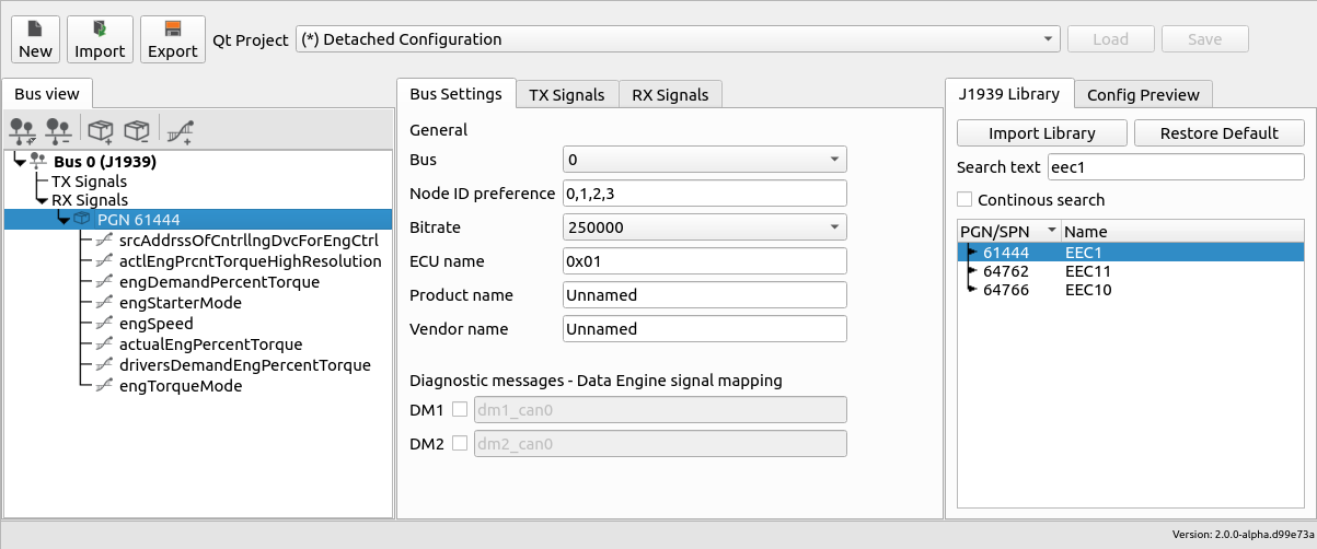
User Interface
The configurator consists of five sections:
Projector selector
Bus view
Bus settings and TX/RX signals
Library view and file previews
Footer
Project selector
The top part of the configurator holds the project selector. The drop-down lists all opened projects in Qt Creator. It allows for swapping between projects that should be updated by the plugin. Any existing settings and configurations are automatically loaded when a project is selected from the list of projects. The selected project is synchronized between all LinX Manager plugins.
Detached Configuration is supported by LinX Manager Fieldbus Access. This mode allows a user to configure and setup a complete system without linking with an actual project. The configuration can be exported and then imported to update another project.
Buttons to create a new configuration, import an existing and export the current configuration is also maintained here.
Bus view
The bus view is located on the left-most side. This tree view shows an overview of created buses (J1939 or CANopen) along with received and transmitted signals. Selected item controls the content found in the middle panel.
Buttons to add and remove buses, PGNs, SPNs, PDOs and signals are located here. The buttons are hidden or visible based on the selected item in the tree view.
Bus settings
The middle panel hosts a tab for bus settings of the selected bus in the Bus view. Many of the settings are common between the J1939 and CANopen protocols, but others are unique based on the chosen protocol.
J1939 settings
| Setting | Description |
|---|---|
| Bus | CAN channel used for communication |
| Node ID preference | 8 bit node address in decimal form |
| Bitrate | Communication speed |
| ECU name | 64 bit value to uniquely identify the ECU in the network |
| Product name | Name of the product |
| Vendor name | Name of the vendor |
Reception of diagnostics messages (DM1 and DM2) can be activated via the checkboxes. This removes the need to manually define them. Adding DM1 and DM2 to the receive whitelist is done automatically by Fieldbus Access if activated. The name can be changed if the suggested name is not to your liking. Note that parsing of incoming DM1/DM2 messages needs to be done in the application.
CANopen settings
| Setting | Description |
|---|---|
| Bus | CAN channel used for communication |
| Node ID | 8 bit node address in decimal form |
| Bitrate | Communication speed |
| On error | Network management (NMT) state on error |
| Product name | Name of the product, stored in EDS |
| Product number | Product code, stored in EDS |
| Vendor name | Name of the vendor, stored in EDS |
| Revision number | Name of the vendor, stored in EDS |
TX/RX signals
The transmit (TX) tab lists signals which are transmitted from Fiedlbus Access to the CAN bus. The receive (RX) tab lists signals which Fieldbus Access reads from the CAN bus.
J1939 signals
The table view lists configured PGNs and their respective SPNs. Adding or removing items from this view can be done using the mouse. Right-click in the table view to open up the context menu to perform actions based on the selected type.
A single PGN consist of the following attributes:
| PGN | Description |
|---|---|
| PGN | Parameter group number (PDU format + PDU specific) |
| Name | Name of the PGN |
| Priority | Default priority |
| Source Address | Accepted source addres (0xFF to accept any source) |
| Transmission Mode | Change of state or cyclic |
| Cyclic Interval | Interval of reception or transmission of PGN |
Each PGN contains one or multiple SPNs. Each SPN will is available as indidivual Data Engine signals in the application once the project is updated.
| SPN | Description |
|---|---|
| DE Signal | Data Engine signal name |
| DE Datatype | Data Engine datatype |
| Byte Position | Byte position of the SPN |
| Bit Position | Bit position of the SPN |
| Bit Length | Bit length of the SPN |
| Gain | Raw value scale factor |
| Offset | Raw value offset |
| Default value | Default value of signal |
CANopen signals
The table view lists configured transmit and received signals as well as transmit and receive PDOs that can be mapped to the created signals. Adding or removing items from this view can be done using the mouse. Right-click in the table view to open up the context menu to perform actions based on the selected type.
A signal consist of the following attributes:
| SIGNAL | Description |
|---|---|
| DE Signal | Data Engine signal name |
| DE Datatype | Data Engine datatype |
| Gain | Raw value scale factor |
| Offset | Raw value offset |
| OD Index | Object dictionary index (fixed, dependent of Datatype) |
| OD Subindex | Object dictionary subindex (fixed, dependent of Datatype) |
| Default value | Default value of signal |
Each PDO contains one or multiple signals. A PDO consist of the following attributes:
| PDO | Description |
|---|---|
| PDO Name | Name of the PDO |
| COB ID | Communication object identifier. Example: 0x181 or $NODEID+0x180 |
| Transmission Type | Transmission Type Table |
| Number of SYNCs | For transmission type Cyclic Synchronous only. Indicate the interval for transmitting the PDOs. The value is a multiple of the Cycle Period (µs) of the CANopen manager |
| Inhibit Time (x100 µs) | The inhibit time is the minimum time between two messages of a specific PDO. You can use this setting for preventing PDOs from being sent too often when their values are edited. Default: "0". Possible values: 0...65535. |
| Event Time (x1 ms) | Only for transmission types Asynchronous Manufacturer Specific and Asynchronous Device Profile. Indicate the time frame that should be between two PDO transmissions PDOs (in milliseconds). Default: "0". Possible values: 0...65535. |
| Total bitlength | Total bitlength of the signals in the PDO. Max total value: 64 |
Transmission type
| Transmission | Type | Description |
|---|---|---|
| Acyclic Synchronous | 0 | An RxPDO is only evaluated after the next SYNC telegram has been received |
| Cyclic Synchronous | 1-240 | In transmission types 1-240 the PDO is transmitted cyclically: after every ”n-th” SYNC (n 1...240) |
| Asynchronous Manufacture Specific | 254 | The PDO is transmitted after specific events |
| Asynchronous Device Profile | 255 | The PDO is transmitted according to the CiA device profile |
Library view
The right-most panel has two purposes: a tab for the J1939 library and tabs for file previews.
J1939 library
The library view is available when a J1939 bus is created. The most common PGNs are available and can be added directly to the current project by dragging a specific PGN from the library and dropping it in the view in the middle (TX/RX signals). When adding PGNs from the library, all SPNs will be automatically assigned a suitable data type to carry physical value.
Use the search field to find specific PGNs, either by their name or assigned parameter group number.
Import library
DBC databases, the widely used file format to describe CAN networks is supported by the tool. PGNs from the database can be added to the configuration once the database is imported. To restore the default library, press the restore button located beside the import button.