How-tos
Update projects
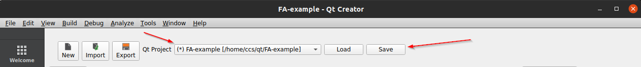
Select a project from the project bar drop-down menu. An asterisk (*) beside the project name will indicate that the configuration has been changed (signal added, renamed or removed). Press “Save” for the changes to take effect.
New files will be generated and stored in the selected projects working directory. These files are then included via
LinXManager.pri by a include directive in the *.pro file. Necessary code to access the configured signals are
injected into main.cpp if the Qt project type is QML.
Supported project types
Both QML and Widget based Qt projects are supported by the configurator. QML projects have enhanced support and are automatically updated with the required code to have direct access in the GUI. Widget based project have the required files added to the project but needs to be included manually in the source.
Generated files
List of files which are generated and stored in the selected project when the configuration is saved:
LinXManager.pri
dataenginebase.cpp
dataenginebase.h
dataengine.cpp
dataengine.h
dataenginesignal.cpp
dataenginesignal.h
idataenginesignalerror.cpp
idataenginesignalerror.h
LinXManager_DE_configfile.json
qtobserver.cpp
qtobserver.h
Specific files generated from LinX Manager Fieldbus and added to the project:
fieldbusaccesserror.cpp
fieldbusaccesserror.h
fieldbusaccesserrormodel.cpp
fieldbusaccesserrormodel.h
LinXManager_FA_configfile.json
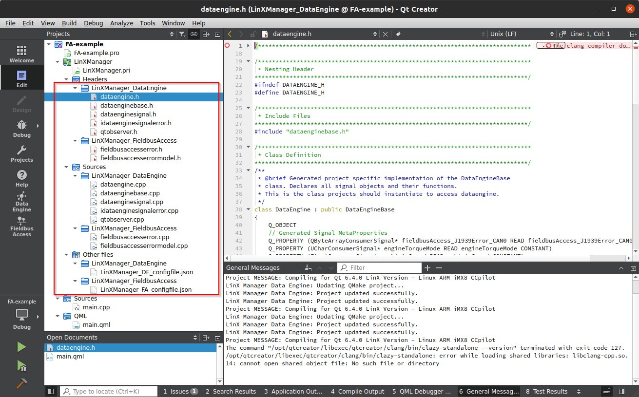
All the files can be seen in Qt Creator Project window:
Revert current changes
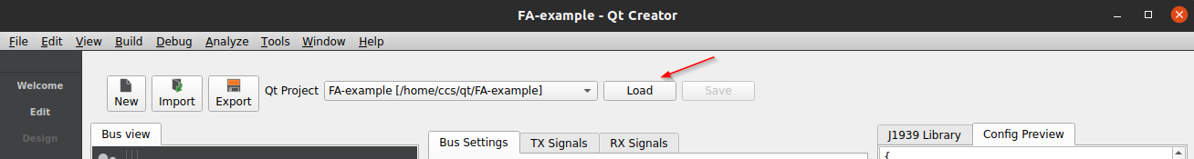
Use the “Load” button to restore the last known configuration and reject current changes.
Deploy and run Fieldbus Access with generated configuration
Configuration install path
Qt projects updated with the tool will have the Fieldbus Access configuration file added to the list of files to install when the project is deployed to a remote device.
Default target path for projects based on the CrossControl project templates are /opt/{TARGET}/bin where TARGET is the base name of the project file by default.
This results in a file path for the configuration: /opt/{TARGET}/bin/LinXManager_FA_configfile.json.
Update default Fieldbus Access configuration
A default configuration is added when Fieldbus Access is installed on the device, found at
/opt/bin/FieldbusAccess_ConfigFile.json. Fieldbus Access will read this configuration files by default. To load a
project specific configuration, replace the default configuration with a symbolic link, pointing to the deployed
configuration.
Connect to your device via
ssh.Update the default FA configuration to point to your deployed configuration:
ln –sf /opt/{TARGET}/bin/LinXManager_FA_configfile.json /opt/bin/FieldbusAccess_ConfigFile.jsonReboot the device for the changes to take effect.
There is no need to re-do the symbolic link once created. New configuration files can be deployed directly from Qt Creator. Remember to reboot the device for the configuration to be read.
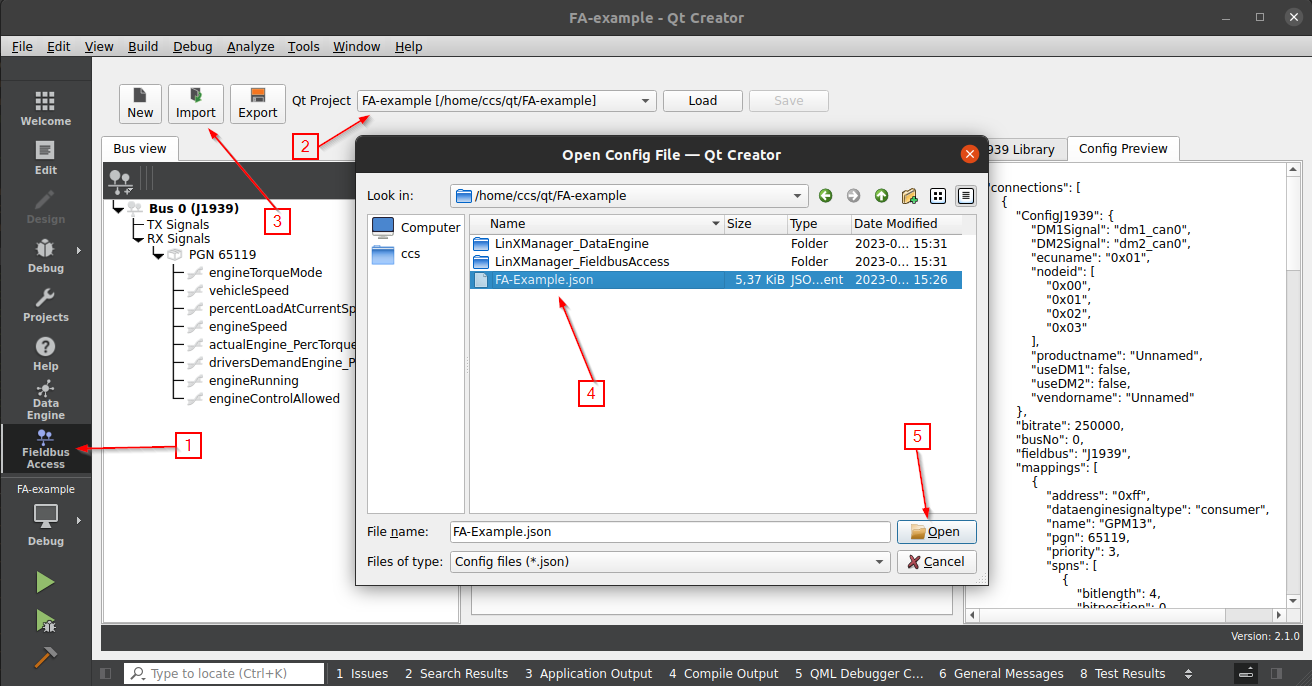
Import a configuration
The import feature allows a project to be updated with a predefined/reused configuration.
Open LinX Manager Fieldbus Access from the mode selector.
Select the project from the project selector drop-down menu which should be updated.
Press on the “Import” button located in the top bar.
Locate a LinX Manager Fieldbus Access configuration (*.json) to import.
Project is updated with the content read from the configuration.
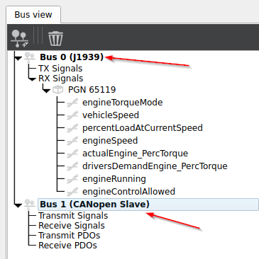
Create multiple CAN buses
Fieldbus Access can handle communication with multiple CAN buses at the same time.
Create a new CAN bus by pressing the add button
 and select
“Add new J1939 bus”.
and select
“Add new J1939 bus”.Repeat step one and create as many CAN buses that are needed.
Each new bus will by default be assigned the next free bus number (first instance is given 0, next 1…). Adjust when needed.
Create custom J1939 PGNs
Custom PGNs is supported if a certain PGN is not available in the library or the CAN network include nodes which use customer specific PGNs.
Create a new CAN bus by pressing the add button
and select
“Add new J1939 bus”.Select “RX Signals” in “Bus view” and press
 to create a new
PGN.
to create a new
PGN.Select the created PGN in the “Bus view” and press
 to create
new SPNs for the PGN.
to create
new SPNs for the PGN.Update PGN and SPNs with information about the PGN and associated SPNs.
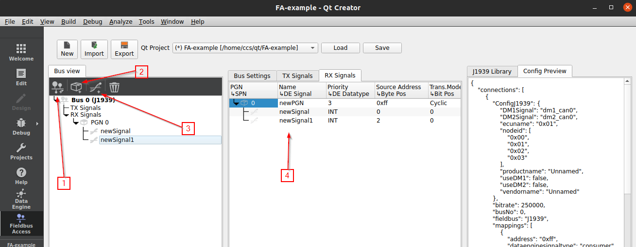
An example how to create a custom PGN can be found in J1939 examples.
Receive and transmit PGN with dynamic length
Certain parameter groups may require more than the 8 bytes supported by the CAN standard. Packaging and reassembly of messages larger than 8 bytes (up 1785 bytes) is all taken care of by the Fieldbus Access runtime.
Reception and transmission of PGNs which require more than 8 bytes is achieved by defining a single SPN in the PGN and assigning it BLOB as the datatype, for example:
| SPN / DE Signal | DE Datatype | Byte Pos. | Bit Pos. | Bit Len. | Gain | Offset |
|---|---|---|---|---|---|---|
| serialNr | BLOB | 0 | 0 | 64 | 1 | 0 |
A SPN which is configured as BLOB, it will carry the source address in the first byte when the application receives it. This is useful if the SPN can be received from multiple sources.
| Byte | Data description |
|---|---|
| 0 | Source address |
| 1-N | Message data |
It is required to set transmission mode to “Change of state” for PGNs which have message lengths larger than 8 bytes.
Import J1939 DBC database
Create a J1939 bus if not already created (this will display the “J1939 Library” tab in the right-most panel).
Press “Import Library”.
Locate DBC to import and press Open.
Library is populated with content found in the DBC.
Drag and drop PGNs from the library to the TX/RX panel
Configuration is updated with information from each dropped PGN.
Access signals from the UI
QML
Qt projects based on the CrossControl Qt Quick 2 Application project template are prepared to work directly with the
configurator. LinX Manager Fieldbus Access injects main.cpp with the required code to make the configured signals
available directly in QML. Each configured signal is available as a Q_PROPERTY in the DataEngine class. The instance
is accessible in QML via the context property called dataEngine.
QQuickView *view = new QQuickView;
// <LINX MANAGER> //
...
DataEngine dataEngineContext;
qmlRegisterUncreatableType<DataEngine>("CrossControl", 1,0, "DataEngine", "Don't instance DataEngine");
view->rootContext()->setContextProperty("dataEngine", &dataEngineContext);
// </LINX MANAGER> //
Read signals from QML
Text {
    text: dataEngine.engineRPM.value
}

Gauge {
    minimumValue: 0
    maximumValue: 100
    value: dataEngine.oilPressure.value
}

StatusIndicator {
    active: dataEngine.engineError.value
    color: "red"
}
Write signals from QML
Slider {
    from: 0
    to: 100
    value: 50
    onValueChanged: dataEngine.heatLevel.value = value
}

Button {
    text: "Request stop"
    onPressed: dataEngine.requestStop.value = true
    onReleased: dataEngine.requestStop.value = false
}
Widget
The configurator has basic support for Widget projects based on the CrossControl Qt Widget Application project
template. Generated files are added to the project (headers and classes needs to be imported manually):
Read and write signals from widgets
Example how to add DataEngine to widget class Application and connect two configured signals to local slots:
// application.h
#include "LinXManager_DataEngine/dataengine.h"
class Application : public QWidget
{
    Q_OBJECT

public:
    explicit Application(QWidget *parent = nullptr);
    ~Application();

public slots:
    void setEngineRpm(int value);
    void setOilPressure(int value);

private:
    Ui::Application *ui;
    DataEngine dataEngine;
};
// application.cpp
#include "application.h"
#include "ui_application.h"

Application::Application(QWidget *parent) : QWidget(parent), ui(new Ui::Application)
{
    ui->setupUi(this);
    connect(dataEngine.engineRpm(), &IntConsumerSignal::valueChanged,this,&Application::setEngineRpm);
    connect(dataEngine.oilPressure(), &IntConsumerSignal::valueChanged,this,&Application::setOilPressure);
}
Receive and transmit CANopen PDO
Create one or more signals. They could be of type transmit or receive. In the Transmit tab, right mouse click and create a new transmit signal.
| DE Signal | DE Datatype | Gain | Offset | OD Index | OD Subindex |
|---|---|---|---|---|---|
| newSignal | INT | 1 | 0 | 2270 | 1 |
Next we want to map this signal to a TPDO. In the TPDO mapping tab, right mouse click and “Add a new PDO”.
| PDO Name | COB-ID | Tranmission Type | SYNCs | Inhibit T | Event T | Tot b. |
|---|---|---|---|---|---|---|
| TPDO_1 | $NODEID+0x180 | Cyclic-Synchronous | 10 | 0 |
Then add the created signal to the PDO. On the TPDO_1, right mouse click and “Add signal”.
| PDO Name | COB-ID | Tranmission Type | SYNCs | Inhibit T | Event T | Tot b. |
|---|---|---|---|---|---|---|
| TPDO_1 | $NODEID+0x180 | Cyclic-Synchronous | 10 | 32 | ||
| newSignal | 2270 | 1 | INT | 32 |
Double click the signal name newSignal for a list of possible signals to select from (created transmit signals if in TPDO tab). Edit signal and PDO values as needed.
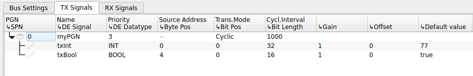
Set default values
You can also access and set default values of data engine signals via the fieldbus access plugin. Below
you see some examples of setting signals. Tx signals will be pushed on the bus as soon as the CANopen node are up and running
and the proper SYNC signals are received. Signals without default value will be initialized to zero.
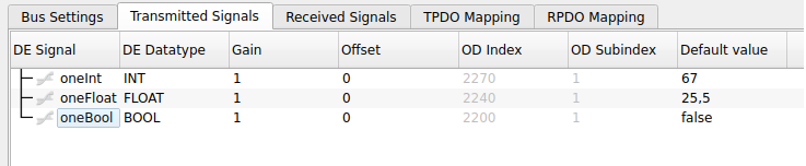
And you can do the same for j1939 signals. See below. Signals without default values will be initialized to 0xff which is standard for J1939.